 Deutsch (Deutschland)
 The Automatic Flight Control System is a three-axis autopilot. It controls the pitch and roll axes and supports limited steering around the yaw axis. On the other hand, the power supply via the collective must be taken over by the pilot himself.
For a realistic flight experience and to fully utilize the AFCS's functionality, we strongly recommend using a high-precision joystick with a strong centering spring. Non-centering joysticks are optionally supported in the PLUS version, but are subject to limited functionality.
When AFCS is installed and not activated, AUTOPILOT caution comes on while collective lever is raised more then about 30 %. This is only for information of pilot. Acknowledge the caution by pressing SELECT on CAD or CDS/AUDIO RESET on cyclic stick and ignore it if you want to fly without autopilot.
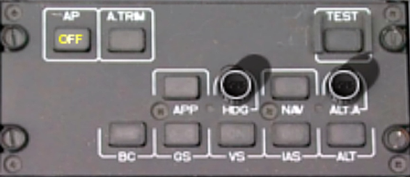
Control Panel for AFCS is installed in the slant console or the center console, depending on other equipment.
In addition the the Control Panel, the AFCS is controlled via the BEEP TRIM and FTR Trim functions.
The current status of the autopilot can be read from the lamps in the buttons of the control panel and, more conveniently, in the PFD.
In the standard configuration, the AFCS obtains its reference data from the sensors that feed the HSI on the pilot's side. The MASTER switch in the center console can be used to switch the data source to the co-pilot's side. The switch position L represents the co-pilot's (left) side, and the switch position R represents the pilot's (right) side. The selected source is indicated in the ND by a box surrounding the selected source name. If GPS (NMS) is selected as the source, when feeded from the pilot's side, it is always the right GPS device, and when feeded from the co-pilot's side, it is always the left GPS device.
Engagement and Disengagement of AFCS
AFCS is engaged by pressing AP button. Amber indication light OFF will disappear. System is now active in A. TRIM mode.
Pressing AP button again will disengage AFCS. Pressing SAS/AP CUT button at cyclic stick will also disengage AFCS and additionally all SAS functions. When AFCS is disengaged amber OFF in AP button is illuminated.
After disengaging AFCS warning light AP A.TRIM, caution AUTOPILOT and warning gong come on for 10 seconds.
A. TRIM Mode
A.TRIM is the basic mode of the AFCS. It maintains the helicopter's flight attitude in pitch and roll axis. In a fixed-wing aircraft, this corresponds to the combination of wing leveler and pitch hold. A.TRIM is automatically active when the autopilot is switched on. While A. TRIM mode is active, amber indication OFF in A. TRIM button is off. AFCS's status lines in PFD are empty.
Override: Moving the stick out of its central position overrides temporarily the autopilot. When the stick is returned to its centered position, the autopilot returns to the previous reference attitude.
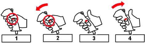
BEEP TRIM forwards or afterwards change reference attitude in pitch, BEEP TRIM left or right change reference attitude in roll.
FTR Button can also be used to change the reference attitude as descibed below.
- Press FTR.
- Fly hands-on to the desired attitude in pitch and roll while holding FTRpressed.
- When desired attitude is reached, release FTR button.
- Let the stick immediately after releasing FTR go back to it's centered position.
Follow-up Mode
Follow-up mode is a special form of A. TRIM mode. It is automatically activated when airspeed is below 30 kt. This mode simplifies control of the helicopter during hovering, takeoff, and landing. The attitude reference follows all stick movements.
Once the stick has been held in a stable position for approximately min. 1 second, the stick can be returned to its centered position at any time without changing the flight attitude. This allows for very comfortable trimming and fatigue-free flying with minimal effort. This feature is not available if a non-centering stick is configured.
When exiting follow-up mode because the speed exceeds 30 kt, the attitude reference is transferred unchanged to A. TRIM mode at the moment of transition. Conversely, when entering follow-up mode because the speed falls below 30 kt, the reference is also retained.
FTR has no function in Follow-up mode.
Upper Modes
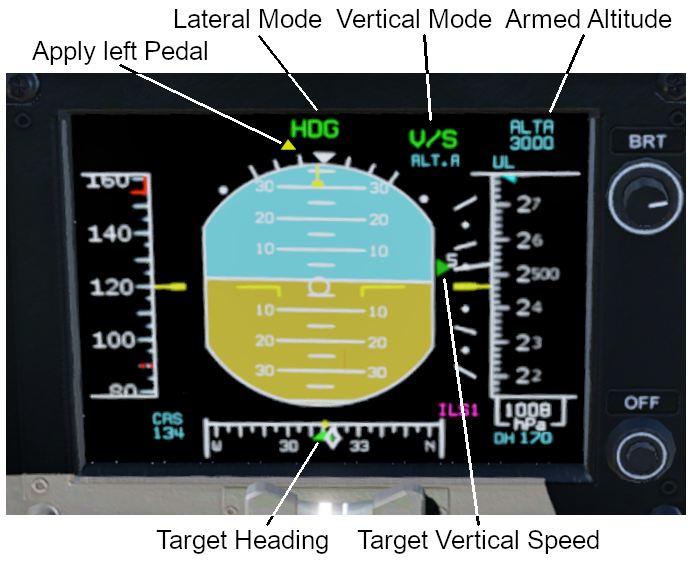
In addition to A. TRIM Mode AFCS provides 10 Upper Modes. When an upper mode is armed an amber indication light A is illuminated in the respective button, when engaged a green C (coupled) or ON comes on. Activated HDG or ALT.A Mode is indicated by a green ▸ next to the caption. Active upper modes are indicated by green text in the PFD strip. For horizontal modes, this text is centered above the attitude indicator; for vertical modes, it is positioned to the right of it. Armed upper modes are indicated by cyan text.
Upper modes can only be activated if AFCS is on.
When an upper mode is disengaged caution DECOUPLE will come on for 10 s at CAD. Pressing A. TRIM button will disengage all upper modes an switch to AFCS SAS mode.
All upper modes can only be activated at a speed of 40 kt. ALT, ALT.A, and VS have speed protection at 60 kt. Most other upper modes are automatically decoupled at speeds below 26 kt.
ALT Mode
Holds altitude (vertical mode).
Engage: Press ALT button.
Disengage: Press ALT button oder select other vertical mode.
Override: BEEP TRIM forwards and afterwards change reference altitude.
IAS Mode
Holds indicated airspeed (vertical mode).
Engage: Press IAS button.
Disengage: Press IAS button oder select other vertical mode.
Override: BEEP TRIM forwards and afterwards change reference speed.
VS Mode
Holds vertical speed (vertical mode).
Engage: Press VS button.
Disengage: Press VS button oder select other vertical mode.
Override: BEEP TRIM forwards and afterwards change vertical speed.
GS Mode
Follows glide path of an ILS (vertical mode). At approx. 65 ft above the ground, the mode reverts automatically to the ALT mode to get the helicopter levelling off.
Engage: Press GS button.
Disengage: Press GS button oder select other vertical mode.
HDG Mode
Holds heading (lateral mode).
Engage: Press HDG button. Set desired heading with HDG rheostat. Target heading is set to the current heading. Or: Set desired heading with HDG rheostat. A cyan bug shows the target heading. Press HDG button to engabe HDG mode.
Disengage: Press HDG button or select other lateral mode.
Override: BEEP TRIM left or right and HDG rheostat change reference heading.
APP Mode
Follows VOR or locator of an ILS (lateral mode).
Engage: Tune in frequency of VOR or ILS. Press APP button. APP mode will be armed and automatically engaged when the nav source is captured. As long as APP mode is armed another active lateral mode stays engaged.
Disengage: Press APP button or select other lateral mode.
NAV Mode
Follows a course given by GPS/NMS, VOR or HSI (lateral mode).
Engage: Tune in frequency of VOR or programm GPS/NMS. Press NAV button. NAV mode will be armed and automatically engaged when the nav source is captured or GPS/NMS is selected. As long as NAV mode is armed another active lateral mode stays engaged.
Disengage: Press NAV button or select other lateral mode.
ALT.A Mode
Acquires and executes an automatic level–off and capture of a predefined barometric altitude (vertical mode).
ALT.A uses VS mode implicitly and changes to ALT when target altitutde is reached.
Engage: Select target altitude by ALT.A rheostat. Press ALT.A button. Default vertical speed is 500 ft/min. If current veritcal speed is greater than this, the current speed will be set.
Disengage: Press ALT.A button or select other vertical mode.
Override: BEEP TRIM forwards and afterwards change vertical speed.
GA Mode
Go Around Mode is used to abort approach. It will hold a indicated airspeed of 75 kt.
Engage: Press GA button at collective lever (assign the joystick command sim/autopilot/take_off_go_around to a button).
Override: BEEP TRIM forwards and afterwards change reference speed.
BC Mode
Back Course Mode is not supported.
Steering around the yaw axis
When the AFCS is active in A. TRIM mode or one of the upper modes (not in SAS mode), it also assists the pilot with steering around the yaw axis. However, the authority of the corresponding actuators is limited to 9.25% of the total control travel. Therefore, the pilot must make an appropriate initial setting. Amber triangles on the left and right edges of the display for the selected horizontal mode indicate when pilot intervention is required.
If a triangle appears on the left, the pilot must apply left pedal pressure; if it appears on the right, the right pedal must be pressed. With cautious control inputs, as long as the triangle is illuminated, this has no effect on the steering; it only compensates for the actuator. With more pronounced inputs, steering around the yaw axis is possible despite the triangle being visible.
AFCS SAS Mode
Pressing the A.TRIM button when the AFCS is switched on activates the digital Stability Augmentation System. This is indicated by an amber OFF in the A.TRIM button and amber R and P indications in the PFD strip. In this mode, the autopilot no longer controls the helicopter. Instead, it provides the same functions as the normal SAS, but controlled by the AFCS.
Test of the AFCS
Pressing the TEST button automatically tests the AFCS's functionality. This triggers various indicators on the PFD strip and displays several cautions in the CAD. The indicator lights in the control panel buttons also light up in different ways. The TEST indicator in the button flashes. During the test, the (virtual) stick in the 3D cockpit is also moved automatically.
The test may only be initiated when the helicopter is on the ground, the collective is in its down position, and the autopilot is disengaged.
It is important that the stick is not locked, otherwise it cannot be moved and this will cause an error in the test program.
If the test is successfully completed, the OFF indicators for horizontal and vertical mode appear on the strip, the TEST lamp turns off, and all AFCS-related cautions disappear.
If errors are detected during the test, the TEST lamp remains lit, and any cautions may remain in the CAD. Pressing the TEST button confirms the error. The AFCS must not be used.
Limitations of the AFCS in the simulation
In a real helicopter, the autopilot moves the stick via actuators. This option isn't available in the Home Cockpit. This leads to different behavior depending on the type of joystick used.
Centering Joystick
With a centering joystick, this only becomes significant when a trim is being performed. When pressing BEEP TRIM, the associated stick movement is not perceived on the physical joystick, but only on the animated stick in the 3D cockpit.
Trimming with FTR does not cause the stick to remain in its new position when the button is released. Instead, you have to let it return to the center point.
Once the trimming process is complete, the feel of the stick is absolutely realistic.
Non-Centering Joystick
If a non-centering joystick is used, a realistic flight experience is unfortunately not possible. Firstly, there is no guarantee that the stick will return to its exact position after a temporary override by moving the stick. It is therefore not possible to determine with absolute certainty whether the override should actually be terminated.
It can also happen that the actuators are saturated because the joystick is positioned in an unfavorable way, counteracting the actuator's performance. This problem occurs around the pitch axis. In this case, realistic hands-free flying is no longer possible. The pilot must therefore adjust the stick until sufficient control authority is restored. There are amber triangles above and below the vertical mode indicator in the PFD that indicate the direction in which the stick needs to be moved. The tracking movement must be gentle so that it is not misinterpreted as an override.
This workaround makes it possible to use the autopilot with a non-centering joystick. This behavior can be configured by selecting in the menu. The setting is saved when X-Plane is closed and remains the same the next time it is loaded.